 載入中...請稍候...
- 首頁
- Module
- Channel Relay Module
- Relay Module 5V - 8 channel
產品介紹
Introduction
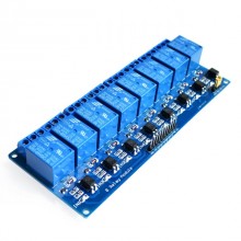
This is a 8-channel LOW level trigger relay and it can be applied to Arduino and Raspberry Pi. Relays are suitable for driving high power electronic devices such as lights, electric fans and air condition. A relay can be used to control high voltages with a low voltage by connecting it to an MCU.
Principle of relay
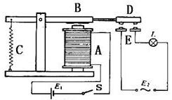
See the picture below: A is an electromagnet, B armature, C spring, D moving contact, and E fixed contacts. There are two fixed contacts, a normally closed one and a normally open one. When the coil is not energized, the normally open contact is the one that is off, while the normally closed one is the other that is on.
Add a certain voltage to the coil and some currents will pass through the coil thus generating the electromagnetic effect. So the armature overcomes the tension of the spring and is attracted to the core, thus closing the moving contact of the armature and the normally open contact (or you may say releasing the former and the normally closed contact). After the coil is de-energized, the electromagnetic force disappears and the armature moves back to the original position, releasing the moving contact and normally closed contact. The closing and releasing of the contacts results in power on and off of the circuit.
Features
- Support control of 10A 30V DC and 10A 250V AC signals
- 5V 8-Channel Relay interface board
- LOW level trigger, equipped with indicator easy to recognize the working status
- Each relay has NO and NC ports, easier to connect and control the connected devices
- Selection of plastic material for high temperature and better chemical solution performance.
- PCB size: 5.7 x 13.8 cm
Ports Description
Input:
- VCC: Connected to positive supply voltage (supply power according to relay voltage)
- GND: Connected to negative supply voltage
- IN1: Signal(LOW Level) triggering terminal 1 of relay module
- IN2: Signal(LOW Level) triggering terminal 2 of relay module
- IN3: Signal(LOW Level) triggering terminal 3 of relay module
- IN4: Signal(LOW Level) triggering terminal 4 of relay module
- IN5: Signal(LOW Level) triggering terminal 5 of relay module
- IN6: Signal(LOW Level) triggering terminal 6 of relay module
- IN7: Signal(LOW Level) triggering terminal 7 of relay module
- IN8: Signal(LOW Level) triggering terminal 8 of relay module
The meaning of high and low level:
INx stands for the contacts including IN1, IN2, IN3 and other pins in the following part.
Triggered at high level means a forward voltage exists between signal triggering terminal (INx) and negative supply voltage. It generally connects positive supply voltage and triggering terminal together. When triggering terminal has positive supply voltage or reaches triggering voltage, the relay will pull in.
While triggered at low level means the voltage between the signal triggering terminal (INx) and negative supply voltage is 0V, or the voltage at the triggering terminal is lower than positive supply voltage. If it lowers to a triggering voltage, the relay will pull in. It generally connects negative supply voltage and triggering terminal together.
Output:
Each submodular of the relay has one NC(nomalclose), one NO(nomalopen) and one COM(Common). So there are 8 NC, 8NO and 8 COM of the channel relay in total. NC stands for the normal close port contact and the state without power; No stands for the normal open port contact and the state with power. COM means the common port. You can choose NC port or NO port according to whether power or not.
Application
General purpose
Testing Experiment
Experiment Principle:
When a low level is supplied to signal terminal of the 8-channel relay, the LED at the output terminal will light up. Otherwise, it will turn off. If a periodic high and low level is supplied to the signal terminal, you can see the LED will cycle between on and off.
For Arduino:
Step 1:
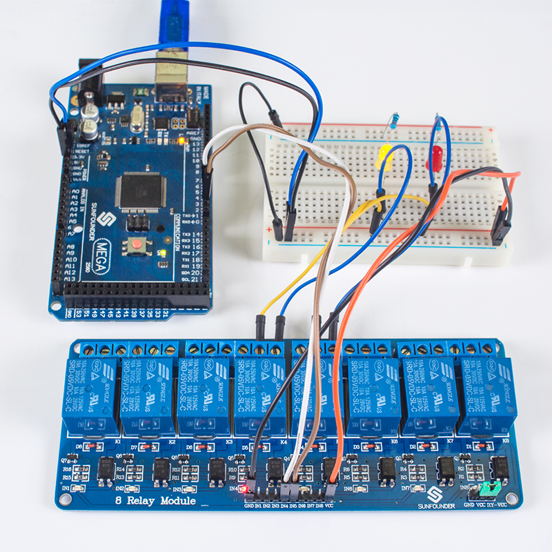
Connect the signal terminal IN4、IN5 of 8-channel relay to digital port 3,2 of the SunFounder Arduino Mega2560 board, and connect an LED at the output terminal.(Pay attention to that there are only two submodules of the 8-channel relay are used in this example, but you can use the 8 submodules freely.)
- 8-channel relay------- Arduino Mega2560
- IN4---------------- 3
- IN5---------------- 2
- 8-channel relay------- Arduino Mega2560
Step 2:
Run the companion procedures 8_channel_relay_lowof the SunFounder Arduino ATMega2560 board,Please see the source code in Resources at the end of the page.Then you can see the LED cycle between on and off.
The actual figure is shown below:
For raspberry pi
Step1:
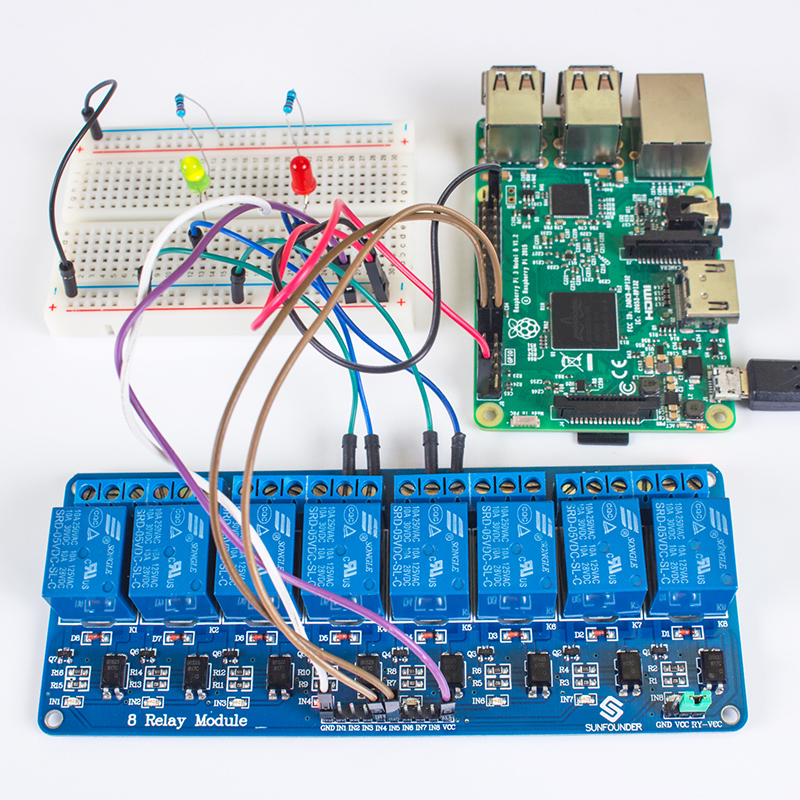
Connect the signal terminal IN4、IN5 of 8-channel relay to port 17,18 of the Raspberry Pi, and connect an LED at the output terminal. (Pay attention to that there are only two submodules of the 8-channel relay are used in this example, but you can use the 8 submodules freely.)
- 8-channel relay--------------- Raspberry Pi
- IN4---------------------- 17
- IN5---------------------- 18
- 8-channel relay--------------- Raspberry Pi
Step 2: Run the Test_code_for_raspberry_pi ,Please see the source code in Resources at the end of the page. Then you can see the LED cycle between on and off.
The actual figure is shown below::


