 載入中...請稍候...
- 首頁
- Module
- Wifi Module
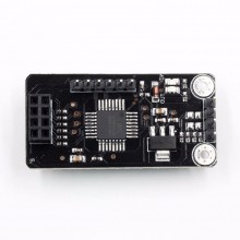
- New ATMEGA48+ NRF24L01
產品介紹
I. Module characteristics:
1) Using the I2C (TWI) communication protocol, the communication process of the NRF24L01 is greatly simplified.
Users do not need to understand the cumbersome communication process of NRF24L01, which greatly improves the project development.
effectiveness.
2) Each module acts as an I2C (TWI) slave (address 35)
3) The module is small and exquisite, 73mm wide and 22mm wide
4) Smooth two-way communication, regardless of slave and host.
5) The maximum transmission distance can reach 70m (for production only)
6) Wireless communication chip is a reliable communication protocol of NRF24L01, reducing data loss
7) The I2C/TWI protocol greatly simplifies the communication lines.
8) Perfectly compatible with arduino
II. Application:
Robot control, remote control, information collection, etc.
Note: Wireless communication may have radiation and is not recommended for life support.
III. Related parameters
Operating voltage: 5V, no short circuit protection circuit, be careful not to reverse the positive and negative poles when using.
Weight: 6g
Module receive data hold time: greater than 2S
Module send data retention time: greater than 300s
Transmission rate: 50Byte/S (theoretical value)
I2C/TWI address: 0x47 (decimal 35)
NRF24L01 address: 0x34, 0x43, 0x10, 0x10, 0x01 (low to high)
Related nouns:
Send data hold means that when the module (TWI slave) receives the data sent by the host, it will send data to another module, and then wait to receive the response signal of another module. If it waits for a period of time, there is no response signal. The module will resend the data, and the number of times the data is repeatedly sent multiplied by the waiting time is the data holding time sent by the module.
The module receiving data retention time means that when the module (TWI slave) receives the data transmitted from the NRF24L01, it shields the NRF24L01 immediately, and the system jumps to wait for the host to take the data. The maximum waiting time is the receiving data holding time.
IV test through compatible devices
VI. Operation Guide
This module adopts I2C/TWI communication mode, which uses NRF wireless module communication, which is safe and reliable. It greatly reduces the loss of data. There are three states in the communication process: MCU read data, free mode (MCU write data or NRF24L01 Write data) module busy (module sends data).
1) The MCU read data status means that the MCU reads the data status of the module. At this time, the module receives the data sent by the NRF24L01 and saves it, waiting for the host to read, (the module LED IN light is on)
Note: The read data status masks the NRF24L01, that is, the NRF24L01 cannot perform any operation on it. At the same time, the read data status has a data hold time. If the hold time is exceeded and the host has not yet read the data, the module automatically jumps to the free mode.
2) Free mode (MCU write data or NRF24L01 write data) means: NRF24L01 module and host (TWI/I2C) can only write to it. (LED OUT/IN are off)
The following possible modules jump to free mode:
1. The module sends the data to the maximum number of times
2. The module successfully sent the data
3. The MCU received the data from the module.
4. Free state exceeds hold time
3) The module is busy. When the module receives the data sent by the host, the module jumps into the busy state and sends data to another module at intervals, while waiting for another module to send a response signal. If after a period of time (module After sending the data hold time), the module will not jump to the free mode. If the response signal is received, the module also jumps to the free mode. (The module LED OUT light is on)
1. Read data data format:
The MCU sends the module address. If the data returned by the module is not "0X47", then the data is proved to be successful.
Only one byte of data can be read at a time
2. Write data format
The MCU sends the module address and sends the data, only one byte of data can be sent at a time and then a stop bit is generated. If the module is busy, it needs to be resent.
Note: When the module is idle, the host read data always reads 0x47.
When the MCU receives data, it must be filtered out 0x47 (decimal 71). Otherwise the program will go wrong.
Use the module for communication experiments:
Experimental conditions:
1. Wireless module two, arduino 328, arduino ADK.
2. Procedures and results:
Description: This experiment is such that the arduino ADK first sends a data, and then waits for reception. If the data is received, the received data is displayed as shown in the above figure COM3, arduino UNO first waits for reception, and then does not receive a data first. Displayed, the data is sent back to the module. This loop


