 載入中...請稍候...
- 首頁
- Display
- Measuring Instrument
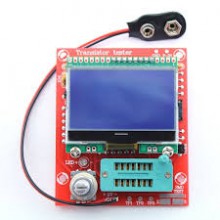
- DIY LCR ESR PWM Graphics Version Transistor Tester
DIY LCR ESR PWM Graphics Version Transistor Tester
產品介紹
Features:
Attention:
The test image is for reference only, please take priority!
This item is a DIY kit, you have to solder it yourself!
1. One key measurement operation, automatic shutdown delay. The off current is only 20nA, battery operation support
2: automatic detection PNP and NPN bipolar transistor, N, MOSFET p-channel, JFET field effect transistors, diodes, two diodes, thyristors, resistors, capacitors, inductors. Automatic detection of current definitions of gain factor (B) and switching on voltage of transistor and emitter connector (Uf), Darlington transistor through high threshold voltage and high gain recognition current.
3: can detect bipolar transistors and internal MOSFET protection diode and display on the screen. The threshold voltage and MOSFET gate capacity can be measured.
4: supports two resistance measurements, potential can also be measured. The highest resolution is resistance measurements of 0.1 ohms, the highest measured value is 50 M Euro.
5: capacitance measuring range from 25pf to 100mF (10 UF). Resolution up to 1 pF. A capacitance of 0.09 UF can be detected above equivalent series resistance (ESR), with a resolution of 0.01 ohms. To view the capacitor voltage loss value and increase the capacity of separate ESR line measurements, available online (on the circuit) direct capacitor and ESR value measurement, easy maintenance and capacity problems solving.
6. Inductance measuring range 0.01 MH-20 H, otherwise it will be displayed as resistance if the inductor's DC resistance higher than 2100 will be displayed as European resistance.
7. Do the two LEDs display the symbols in the right direction, displaying a forward voltage drop. LED detected as diode voltage drop forward higher than normal. Double LEDs detected as a double LED. Simultaneous LED detection flashes, very intuitive.
8. Each time test is about two seconds, only large capacity measurements and high inductance will take a long time
For further function:
1. a square wave signal generator, optionally built-in in the 1 HZ-2 MHZ square wave signal range;
2. PWM pulse signal generator for 1-99% of pulse width modulated signal;
3. Function frequency meter, can test 1 HZ-25 KHZ or higher frequency signal (in this case a slight decrease in accuracy)
Usage:
1. Welding resistors. If you do not know the chromatic circles, check the resistance with a multimeter.
2. Welding other components. Make sure the transistor type and direction are correct.
3. Connect to power (9 V battery or external 5.5 V-12 V DC power supply) instead of connecting to M328 and LCD display. Then measure the voltage between pin 7 and pin 22 with a multimeter. If the voltage is + 5 V, it means that the meter is in normal condition.
4. Cut off the power supply, connect with M328 and LCD display. After installation, connect the power supply.
5. Detailed installation guide: https://www.dropbox.com/sh/uo7nr7xet09esbu/AAAMAjU0sE2hFqCXe0VAsGM_a?dl=0
Technical data:
Display: 12864
Voltage: DC5.5-12V
Current: 24mA
Power supply: 9 V battery (not included)
Resistance measurement: Max.50
Resistance to resolution: 0.1
Capacitance measurement: 25pF ~ 100mF
Capacitance resolution: 1pF
Inductance measurement: 0.01 MH ~ 20 H
Screen size: 5 * 3.5 cm / 2 * 1.4in
PCB size: 7.5 * 6cm / 3 * 2.4in
Package size: 9.5 * 9.5 * 3.5cm / 3.7 * 3.7 * 1.4in
Package weight: 81g / 2.8 oz


